
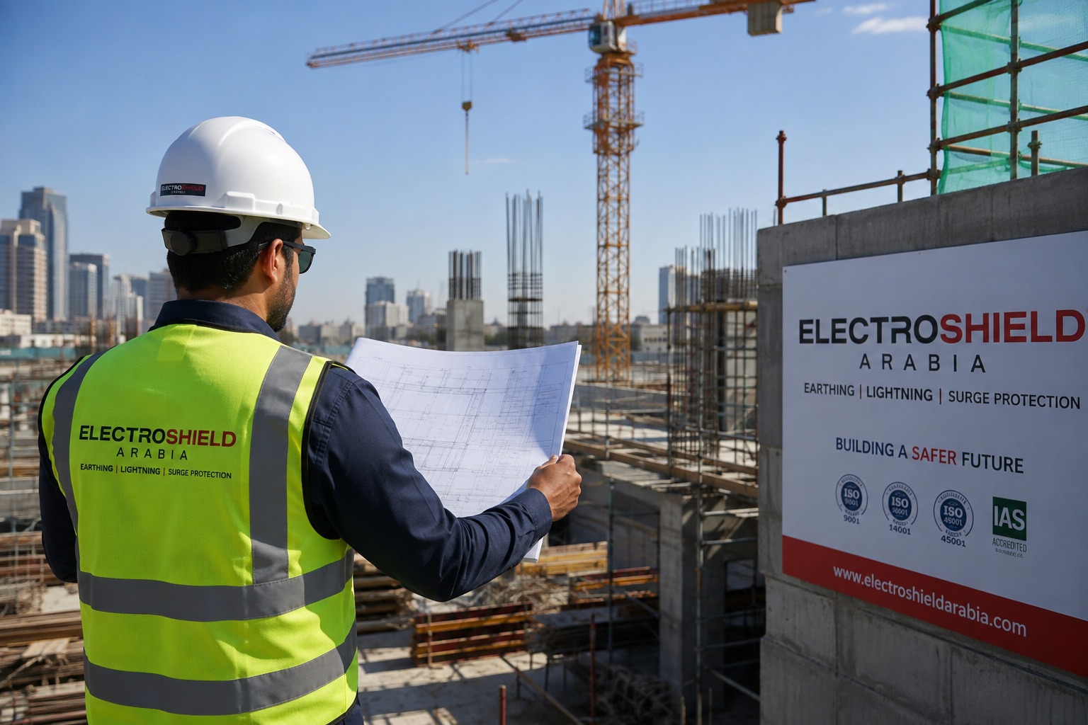
A lightning protection system intercept a lightning strike using air terminals, carries the current safely through down conductors, and dissipates it into the ground through an earth termination network. Earthing resistivity testing happens before any of that design work starts, because soil resistivity determines how many earth electrodes are needed and how they are arranged to hit the target resistance value.
Riyadh doesn’t usually get the same stormy reputation as Jeddah or Abha but talk to someone who’s pulled a summer shift at a substation in the Eastern Province, they’ll set you straight. Thunderstorms pop up across more of Saudi Arabia than people realize, and when lightning strikes something that isn’t protected, it rarely stops at just the point it hits. Electricity moves fast; it’s always looking for the quickest way to the ground. If that path cuts through a building steel frame, some network cabling, or, unfortunately, a technician standing in the wrong place, it turns a simple blown fuse into a much bigger problem.
The Three Parts of a Lightning Protection System
To do the job right, a lightning protection system needs all three parts working together. Leave even one out, and you’re asking for trouble. No single layer can cover the others.
Air terminals, whether traditional Franklin rods, mesh conductors, or Early Streamer Emission (ESE) terminals, are designed to intercept the strike at a predictable point rather than let it hit an uncontrolled part of the structure. Down conductors move the current from where it hits down to the ground, taking the shortest path they can and steering clear of any sharp turns that would slow things down during a lightning strike. In the end, the earth termination network thinks electrodes, conductors, and all the bonding connections spread that current out into the soil.
Here’s the thing most people miss: the earth termination network is not just a grounding rod hammered into the dirt. It is an engineered system sized to the site’s actual soil conditions, and that sizing decision starts with a resistivity test, not a guess.
What Earthing Resistivity Testing Actually Measures
Soil resistivity testing, most performed using the Wenner four pin method, measures how strongly the soil resists the flow of electrical current. Results vary enormously depending on soil composition, moisture content, and depth. Dry sandy soil in parts of the Kingdom’s interior can show resistivity values many times higher than clay rich or moist coastal soil, and that difference changes the entire earthing design.
The design team goes out and takes resistivity readings at different depths and spots around the site. With that data, they figure out how many earth electrodes are needed, how deep they should go, and if they need chemical earthing or extra grid conductors to meet the resistance target. What trips up a lot of projects is skipping this part and just copy pasting electrode numbers from an old job. On paper, the system looks finished. It’s not.
The target resistance itself depends on the application. General lightning protection typically aims for values below 10 ohms. Electrical power systems usually need below 1 ohm. Data centers and other sensitive equipment environments often require 0.5 ohms or lower, sometimes tighter depending on the client specification and applicable standard.
Conventional vs ESE Systems
This comparison comes up in nearly every design conversation, and it deserves an honest answer rather than a sales pitch either way.
Conventional systems, following standards like BS EN 62305 or NFPA 780, use a network of air terminals sized and spaced according to a rolling sphere or mesh method calculated from the building’s risk class. They rely on well established physics with decades of field data behind them, and most international standards of bodies treat them as the baseline approach.
ESE systems, standardized primarily under the French NFC 17102 standard, use a single terminal designed to trigger an upward streamer earlier than a conventional rod would, extending the claimed radius of protection. The catch is that IEC and BS EN standards do not currently recognize the extended protection radius claimed by ESE manufacturers, largely because independent testing has not conclusively validated the early streamer emission effect under natural lightning conditions the way it has under laboratory conditions. That does not make ESE technology useless. It means the protection radius claims need to be evaluated against whichever standard governs the project, and a design based on NFC 17102 assumptions will not automatically satisfy a client requiring BS EN 62305 compliance.
My honest take, after reviewing risk assessments on both types of installations: conventional systems remain the safer specification choice for high risk or high consequence facilities such as petrochemical plants and data centers, simply because the standards backing them carry broader international acceptance. ESE has its place, particularly structures where the reduced terminal count offers a real installation advantage, but it is not a universal substitute.
Bonding and the Part Nobody Photographs
Air terminals and down conductors get attention because they are visible. People don’t usually pay much attention to bonding the things that connect metal structures, pipes, and steel in a building to the same earthing point. That’s a problem. If bonding isn’t done right, a lightning strike can create huge voltage differences between the lightning protection system and other metal parts in the building. That’s when you get side flashes, where electricity jumps across gaps, wrecking equipment or even hurting someone nearby. IEC 62561 covers the components used for this bonding work, and a design that meets air terminal spacing requirements but skips proper bonding calculations is, functionally, an incomplete system.
Testing, Inspection, and the Documentation Gap
You can’t just install a lightning protection system and walk away. Earth resistance needs regular testing because soil conditions change with the seasons. Physical inspections are important to you want to catch corrosion, loose connections, or damage caused by other work around the site. Most standards say you should take a look at least once a year. Bigger tests usually happen based on the code, or anytime there’s a major lightning strike, or if you renovate the building.
The documentation gap is where a lot of projects fall short during consultant review. A finished installation that has no resistivity test logs, no electrode layout drawings, and no commissioning test reports is hard to certify. It is also much harder to defend later if an insurance claim comes up or if someone investigates an incident and asks for proof that the system was set up and built the right way.
Frequently Asked Questions
What is a lightning protection system made of?
Air terminals to intercept the strike, down conductors to carry current to ground, and an earth termination network to dissipate it safely, all tied together with bonding connections to prevent dangerous voltage differences across the structure.
Why is earth resistivity testing done before design, not after?
Because the number and layout of earth electrodes depends directly on how the soil conducts electricity. Designing first and testing later risks an earthing system sized for the wrong soil conditions.
Is ESE lightning better than conventional systems?
No one option is best in every case. Some ESE products advertise a wider coverage range when used under NFC 17102. IEC and BS EN do not accept that stated range. So, what you pick depends on which rules your project must follow. How often should lightning protection be checked? Many standards ask for a yearly visual check. They also require earth resistance tests and continuity checks at set time periods. After a major lightning hit, or if the building structure changes, extra checks are usually expected.
What soil resistivity value requires extra earth electrodes?
There is not one set number. It changes based on the resistance you need for the job. If the soil has higher resistivity, you may need more rods or drives that go deeper. You might also have to add extra steps, such as chemical treatment, to bring the value down to what you require.